
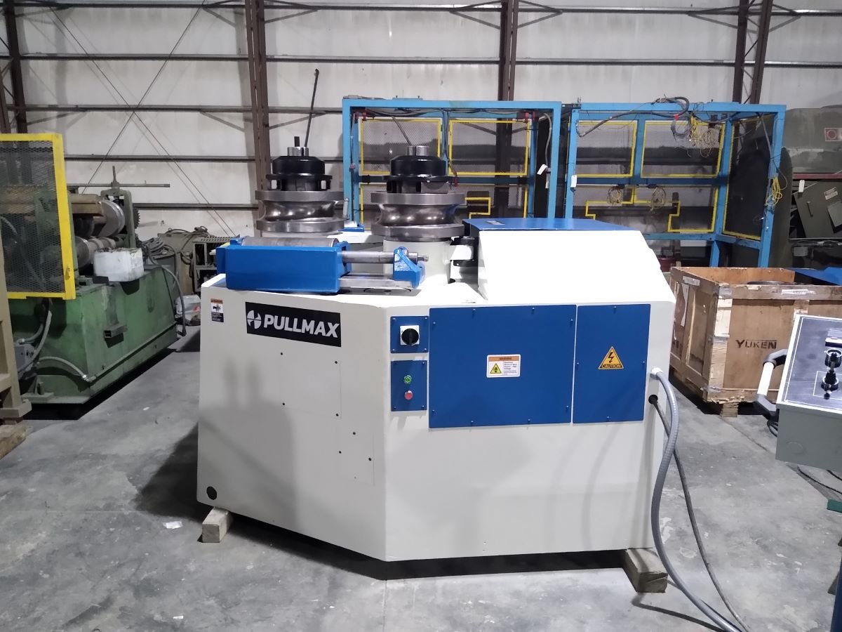
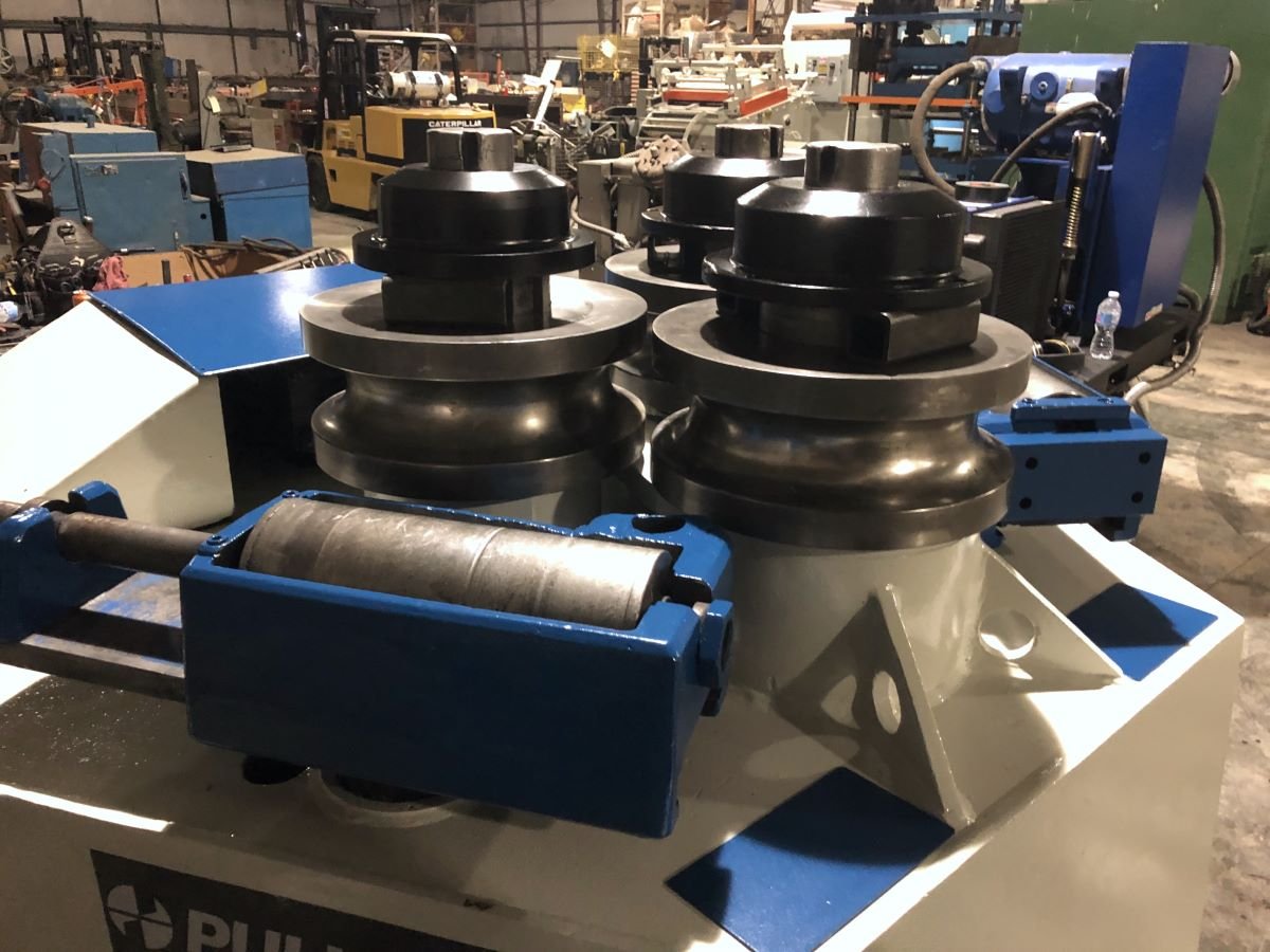
5” x 5” x 1/2” Pullmax Hydraulic Angle Bending Roll, Z-41


sold
-
Manufacturer: Pullmax
Model Number: Z-41
Size / Capacity: 5″ x 5″ x 1/2″ angle
Stock Number: 13412
-
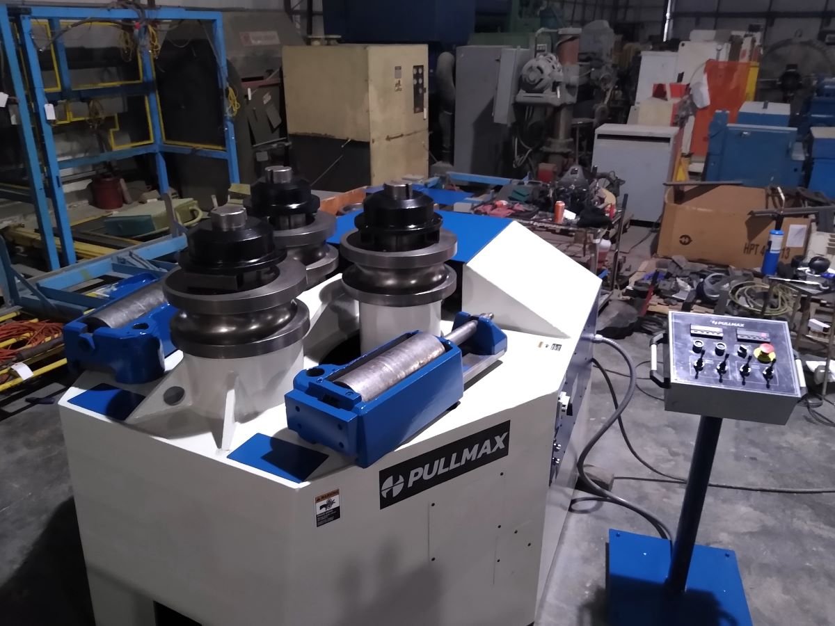
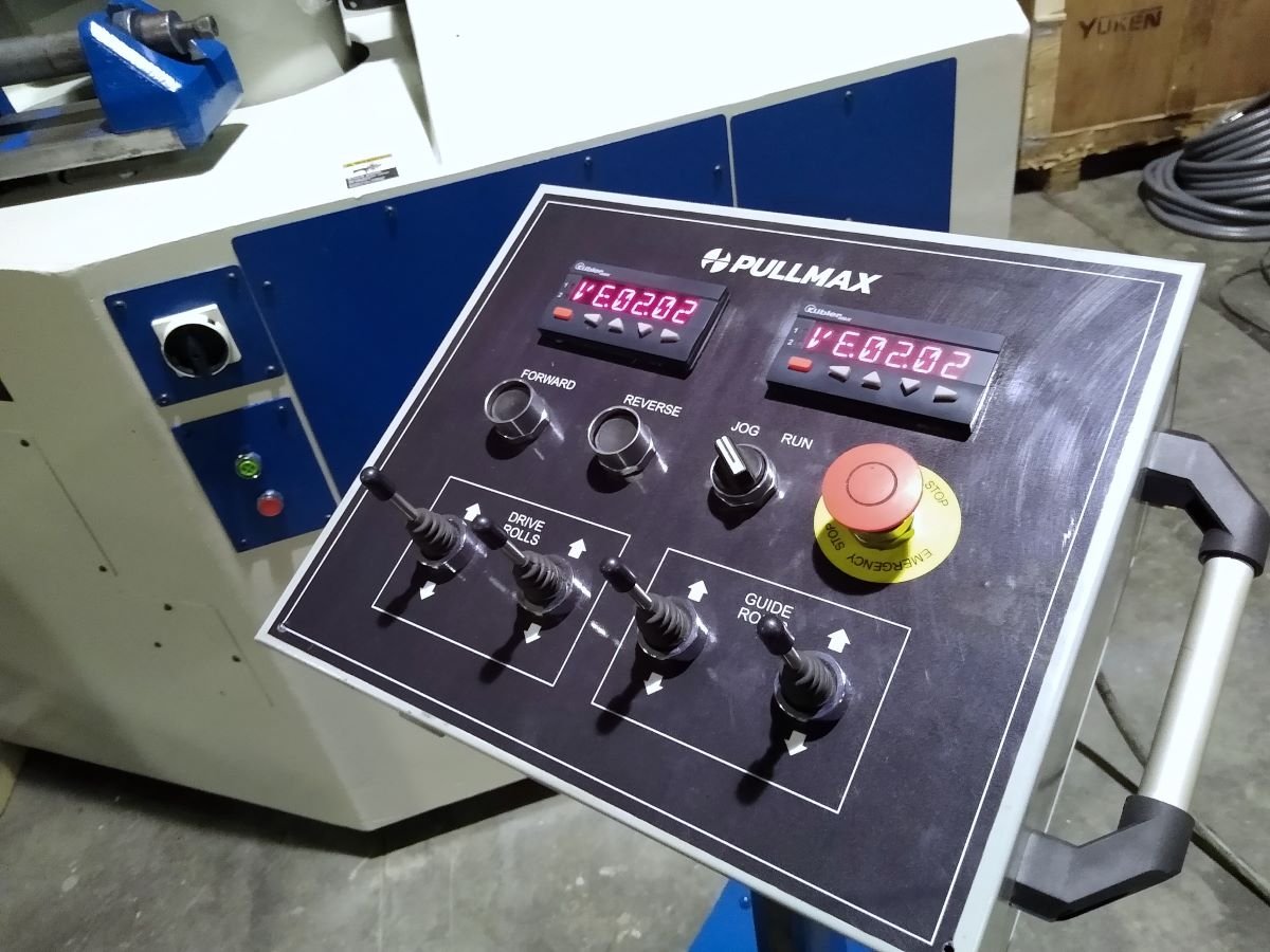
NEW pedestal control stand
NEW Sick wire encoders
NEW Kuebler LED digital displays
Horizontal/Vertical operation
All 3 rolls driven
Hydraulically adjusted guide rolls (*vertical only)
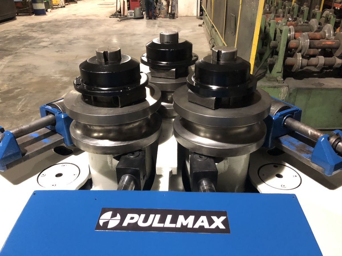
(1) set of dies for angles, channels, tees, flats
(4) sets of pipe dies for 2.5″, 3.0″, 3.5″ & 4.5″ OD
Equipped with additional hydraulic solenoids for optional guide roll adjustment (*in & out) or hydraulic material supports. Machine does not come equipped with either of these options.
-
Angle, leg out
5″ x 5″ x 1/2″ Max. (to 60″ Min. Dia.)
Angle, leg in
4″ x 4″ x 1/2″ Maximum (to 72″ Min. Dia.)
Angle, smallest
1-3/4″ x 1-3/4″ x 1/4″ (to 18″ Min. Dia.)
Flat bar on edge
5″ x 3/4″ (to 50″ Min. Dia.)
Flat Bar, on Flat (Easy Way)
8″ x 1-1/2″ (to 32″ Min. Dia.)
Square bar
2-3/4″ x 2-3/4″ (to 32″ Min. Dia.)
Round bar
3"
Standard St. Pipe
4″ (to 50″ Min. Dia.)
I-Beams, Taper Flanges Web Parallel to Bending Axis, Maximum
10″ x 4″
I-Beams, Taper Flanges Web Parallel to Bending Axis, Minimum
3″ x 2-3/8″
I-Beams, Flanges Parallel to Bending Axis, Maximum
4″ x 2-5/8″
I-Beams, Flanges Parallel to Bending Axis, Minimum
3″ x 2-3/8″
Channels, flange out
10″ x 2-5/8″ Max. (to 70″ Min. Dia.)
Channels, flange in
10″ x 2-5/8″ Max.
Channels, smallest
3″ x 1-1/2″
Tees Leg-In/Leg Out
ST5WF 30 Lbs. (to 60″ Min. Dia.)
Diameter of spindles
3-3/4"
Speed of Rolls Forward & Reverse
8 RPM
Vertical Adjustment of Bottom Rolls
8-1/4″ (Hydraulic)
Guide Rolls Vertical Adjustment
6″ (Hydraulic)
Guide Rolls In & Out Adjustment
5-1/2″ (Hydraulic)
Motor
22 HP
Wired
460 volt
Approximate dimensions
60′ x 70″ x 75″ high
Approximate weight
12,750 lbs.